
JRC Outdoor
Conveyor Rollers
Scroll to Explore
Why JRC conveyor rollers continue
to be used in Japan
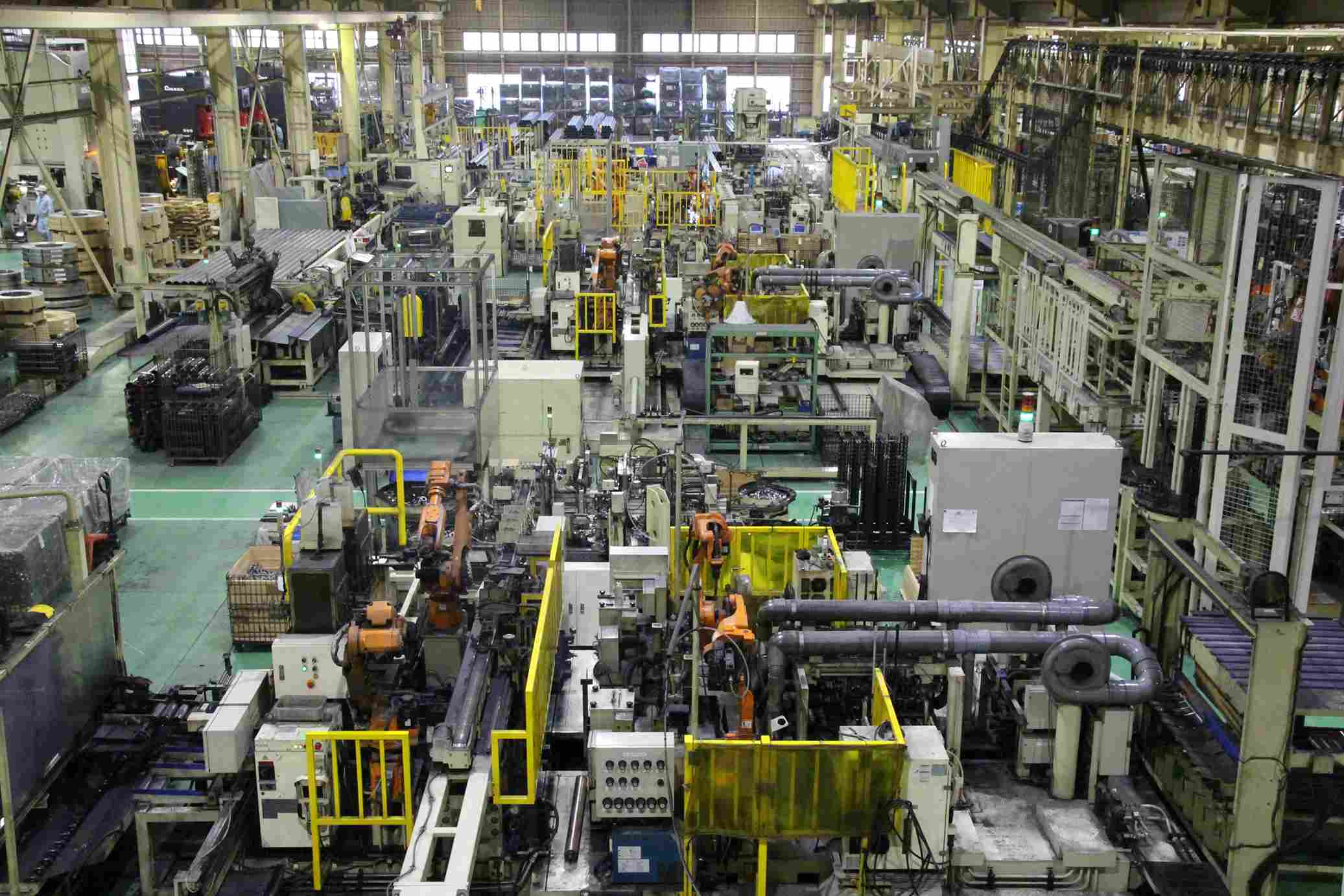
Stable supply system – Trust born from Japanese manufacturing capabilities
- One of the largest production capacities in Japan (approx. 750,000 units per year, 3,000 units per day)
- Stable delivery times thanks to fully automated production lines
- Consistent finish thanks to robot control
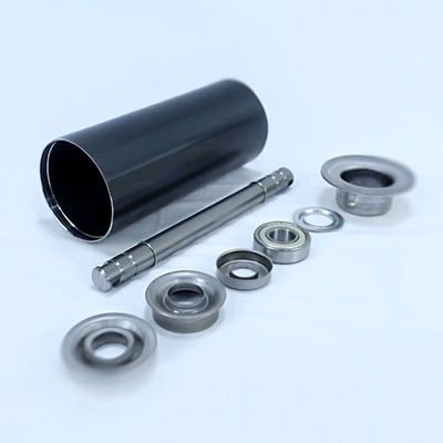
Roller of consistent quality, born from meticulously selected materials and precision machining
- Only materials meeting stringent standards are used
- High-precision machining is strictly enforced for each part
- Precise assembly ensures stable performance even in harsh environments
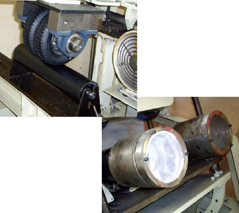
Environmental Testing Beyond the Field – Products Tempered by Harsh Conditions
- Outdoor conveyors are exposed to harsh environments such as dust, moisture, and temperature fluctuations.
- JRC conducts in-house testing under conditions more severe than actual usage environments.
- We leverage this data to continuously improve existing products and develop new ones.
Products Lineup
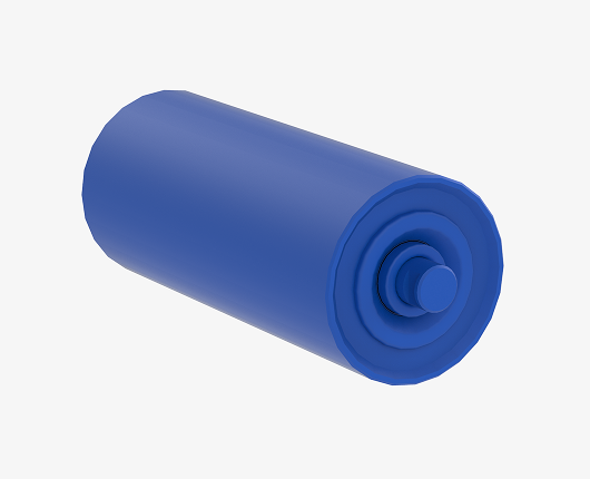
Carrier Roller
- Most commonly used
- Made of steel pipes
- Supports the belt on the load-carrying side (carrier side)
Return Roller
- Most commonly used
- Made of steel pipes
- Supports the belt on the return side
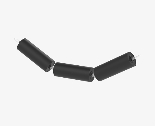
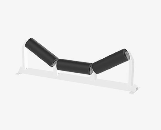
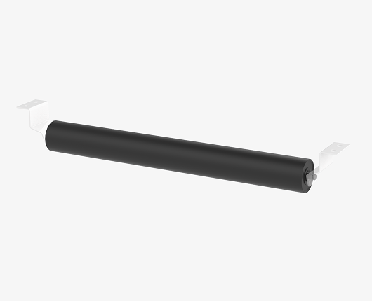
Garland Roller
- Used where belt mistracking or misalignment is likely
- Three rollers connected with a joint link through the shaft end hole, adjusting to the belt during uneven loads, preventing material spillage and mistracking
Dangoless Roller (Non Stick Roller)
- 32° hardness T5 soft rubber (Smart Rubber) is vulcanized onto the surface.
- High rebound elasticity prevents adhesion of wet, high-viscosity, and icy materials to the roller surface
- Excellent wear resistance reduces replacement frequency
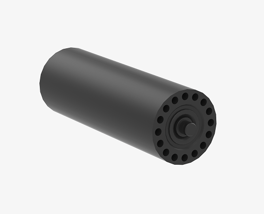
Impact Roller
- Installed at material drop points in conveyor systems (hopper, chute).
- Hollow impact rubber is vulcanized onto a steel pipe roller,
- providing surface durability and shock absorption during material drop.
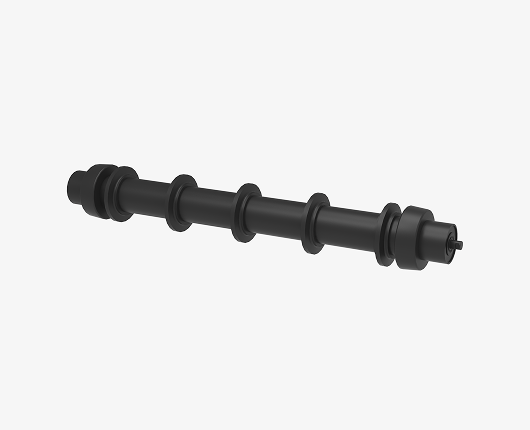
Fall Prevention Return Roller
- Equipped with multiple vulcanized rubber rings on a steel pipe roller.
- Reduces contact area with the belt, minimizing material spillage.
The above represents only a small part of our roller lineup. To learn more about our full product range, please contact us directly.
Product Selection Guide
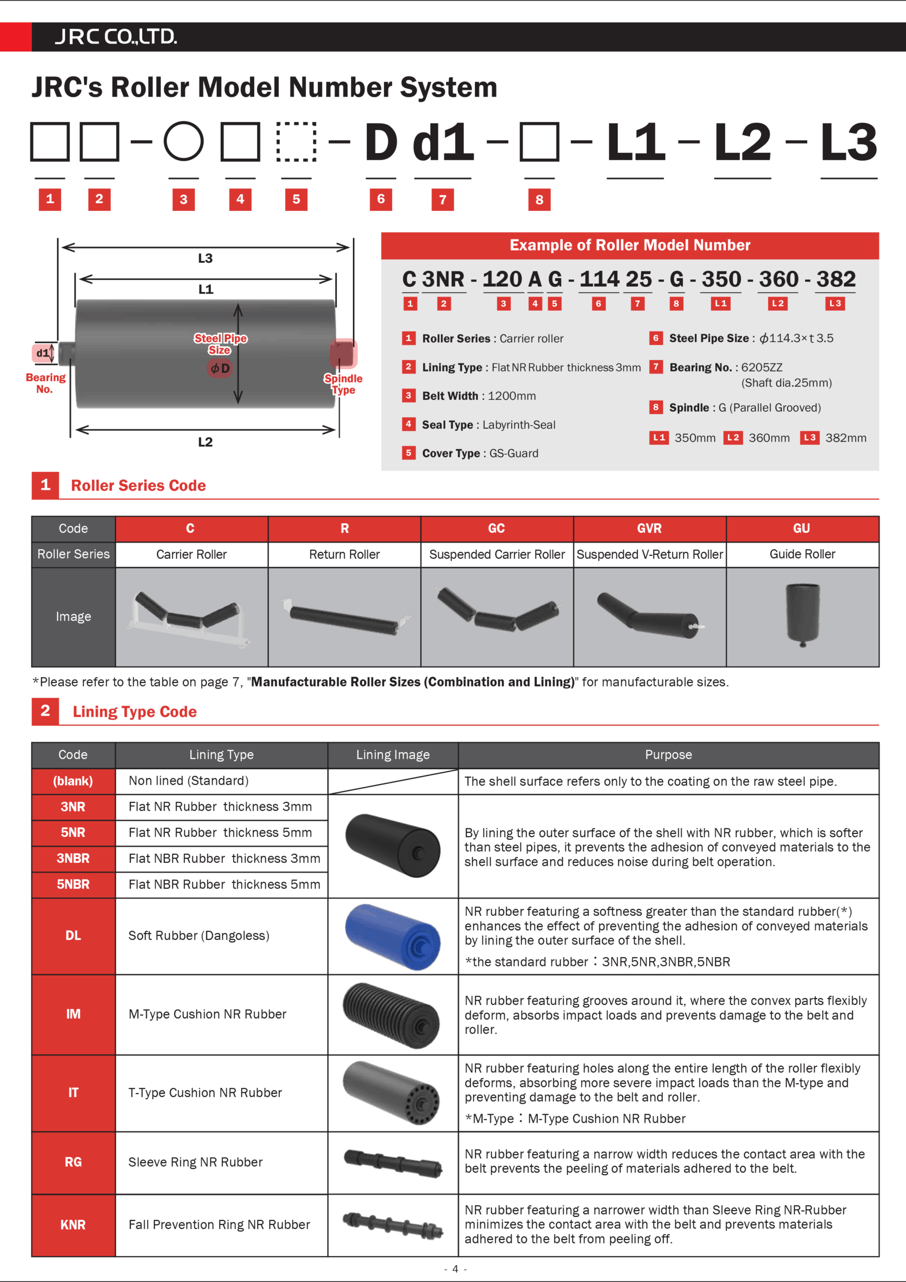
JRC’s Roller Model Number System
1 Roller Series Code
| Code | C | R | GC | GVR | GU |
|---|---|---|---|---|---|
| Roller Series | Carrier Roller | Return Roller | Suspended Carrier Roller | Suspended V-Return Roller | Guide Roller |
| Image |  | 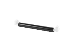 | 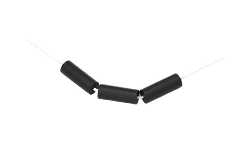 | 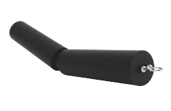 | 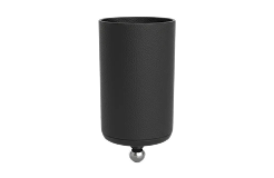 |
*Please refer to the table "Manufacturable Roller Sizes (Combination and Lining)" on this page.
2 Lining Type Code
| Code | Lining Type | Lining Image | Purpose |
|---|---|---|---|
| (blank) | Non lined (Standard) | The shell surface refers only to the coating on the raw steel pipe. | |
| 3NR | Flat NR Rubber thickness 3mm | 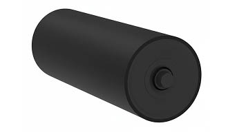 | By lining the outer surface of the shell with NR rubber, which is softer than steel pipes, it prevents adhesion of conveyed materials to the shell surface and reduces noise during belt operation. |
| 5NR | Flat NR Rubber thickness 5mm | ||
| 3NBR | Flat NBR Rubber thickness 3mm | ||
| 5NBR | Flat NBR Rubber thickness 5mm | ||
| DL | Soft Rubber (Dangoless) | 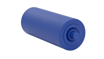 | NR rubber featuring a softness greater than standard rubber enhances the effect of preventing the adhesion of conveyed materials by lining the outer surface of the shell. The standard rubber: 3NR, 5NR, 3NBR, 5NBR |
| IM | M-Type Cushion NR Rubber | 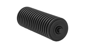 | NR rubber featuring grooves around it, where the convex parts flexibly deform, absorb impact loads, and prevent damage to the belt and roller. |
| IT | T-Type Cushion NR Rubber | 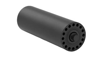 |
NR rubber featuring holes along the entire length of the roller flexibly deforms, absorbing more impact loads than the M-Type and preventing damage to the belt and roller. M-Type: M-Type Cushion NR Rubber |
| RG | Sleeve Ring NR Rubber | 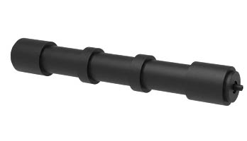 | NR rubber featuring a narrow width reduces the contact area with the belt and prevents peeling of materials adhered to the belt. |
| KNR | Fall Prevention Ring NR Rubber | 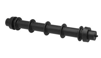 | NR rubber featuring a narrower width than the Sleeve Ring NR Rubber minimizes the contact area with the belt and prevents materials adhered to the belt from peeling off. |
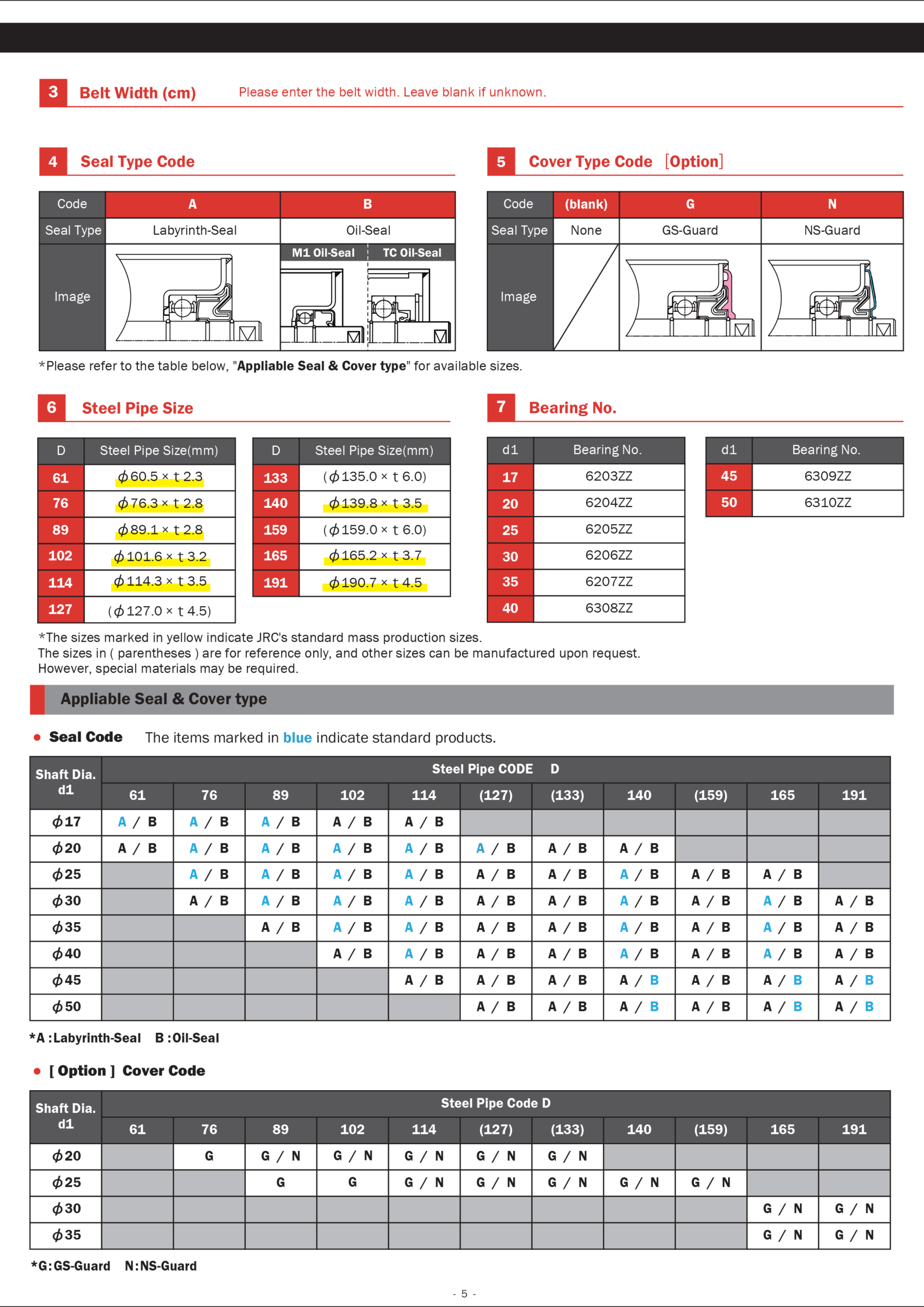
3 Belt Width (cm)
Enter belt width, or leave blank if unknown
4 Seal Type Code
| Code | A | B |
|---|---|---|
| Seal Type | Labyrinth-Seal | Oil-Seal |
| Image | 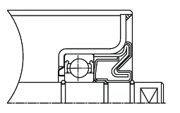 | 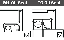 |
5 Cover Type Code [Option]
| Code | (blank) | G | N |
|---|---|---|---|
| Roller Series | None | GS-Guard | NS-Guard |
| Image | 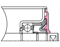 | 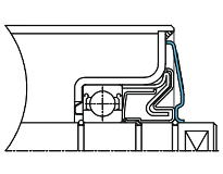 |
Please refer to the table below for available size
Applicable Seal & Cover Type
Seal Code Items marked in blue indicate standard products.
| Shaftt dia.d1 | Steel Pipe CODE D | |||||||||||
|---|---|---|---|---|---|---|---|---|---|---|---|---|
| 61 | 76 | 89 | 102 | 114 | (127) | (133) | 140 | (159) | 165 | 191 | ||
| φ17 | A / B | A / B | A / B | A / B | A / B | |||||||
| φ20 | A / B | A / B | A / B | A / B | A / B | A / B | A / B | A / B | ||||
| φ25 | A / B | A / B | A / B | A / B | A / B | A / B | A / B | A / B | A / B | |||
| φ30 | A / B | A / B | A / B | A / B | A / B | A / B | A / B | A / B | A / B | A / B | ||
| φ35 | A / B | A / B | A / B | A / B | A / B | A / B | A / B | A / B | A / B | |||
| φ40 | A / B | A / B | A / B | A / B | A / B | A / B | A / B | A / B | ||||
| φ45 | A / B | A / B | A / B | A / B | A / B | A / B | A / B | |||||
| φ50 | A / B | A / B | A / B | A / B | A / B | A / B | ||||||
A: Labyrinth-Seal B: Oil-Seal
[Option] Cover Code
| Shaftt dia.d1 | Steel Pipe CODE D | |||||||||||
|---|---|---|---|---|---|---|---|---|---|---|---|---|
| 61 | 76 | 89 | 102 | 114 | (127) | (133) | 140 | (159) | 165 | 191 | ||
| φ20 | G | G / N | G / N | G / N | G / N | G / N | ||||||
| φ25 | G / N | G / N | G / N | G / N | G / N | G / N | G / N | |||||
| φ30 | G / N | G / N | ||||||||||
| φ35 | G / N | G / N | ||||||||||
*G: GS-Guard N: NS-Guard
6 Steel Pipe Size
| D | Steel Pipe Size(mm) |
|---|---|
| 61 | φ60.5 × t2.3 |
| 76 | φ76.3 × t2.8 |
| 89 | φ89.1 × t2.8 |
| 102 | φ101.6 × t3.2 |
| 114 | φ114.3 × t3.5 |
| 127 | (φ127.0 × t4.5) |
| 133 | (φ135.0 × t6.0) |
| 140 | φ139.8 × t3.5 |
| 159 | (φ159.0 × t6.0) |
| 165 | φ165.2 × t3.7 |
| 191 | φ190.7 × t4.5 |
*The sizes marked in yellow indicate JRC's standard mass production sizes.
The sizes in ( parentheses ) are for reference only, and other sizes can be manufactured upon request.
However, special materials may be required.
7 Bearing Number
| D | Bearing No. |
|---|---|
| 17 | 6203ZZ |
| 20 | 6204ZZ |
| 25 | 6205ZZ |
| 30 | 6206ZZ |
| 35 | 6207ZZ |
| 40 | 6308ZZ |
| 45 | 6309ZZ |
| 50 | 6310ZZ |
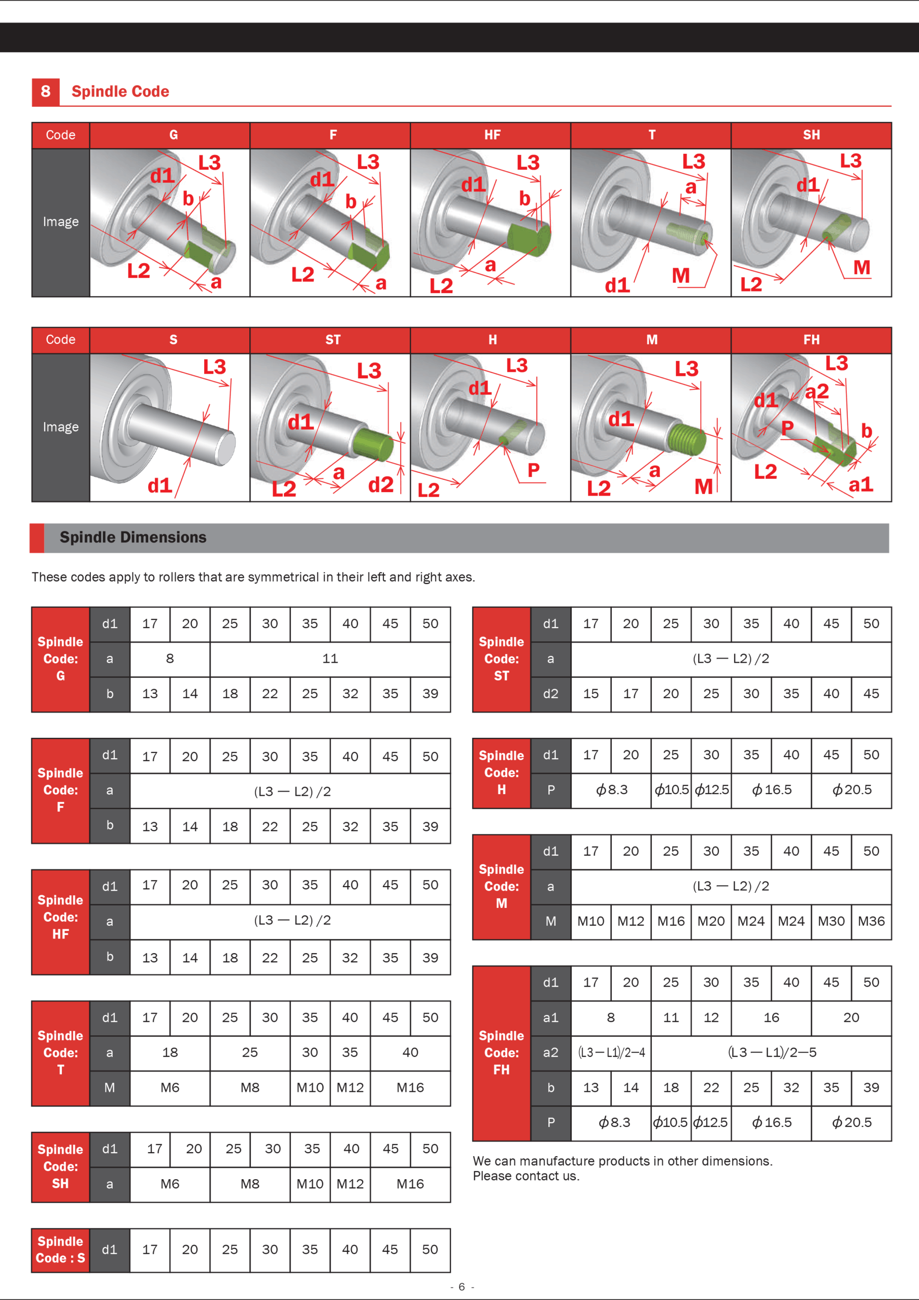
8 Spindle Code
| Code | G | F | HF | T | SH |
|---|---|---|---|---|---|
| Image | 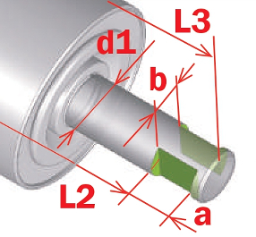 | 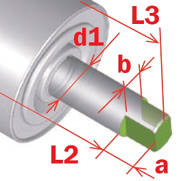 | 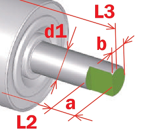 | 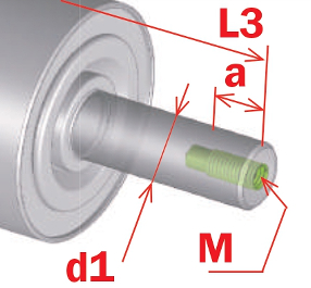 | 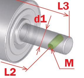 |
| Code | S | ST | H | M | FH |
|---|---|---|---|---|---|
| Image | 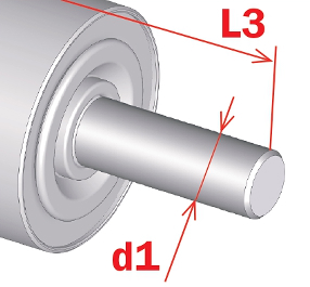 | 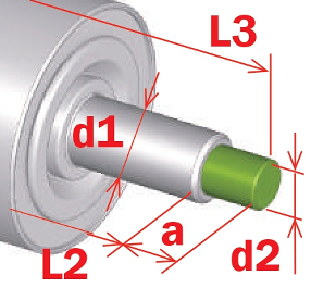 |  | 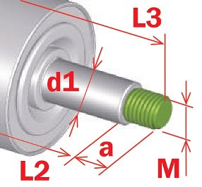 |  |
Spindle Dimensions
These codes apply to rollers that are symmetrical in their left and right axes.
| Spindle Code: G | d1 | 17 | 20 | 25 | 30 | 35 | 40 | 45 | 50 |
|---|---|---|---|---|---|---|---|---|---|
| a | 8 | 11 | |||||||
| b | 13 | 14 | 18 | 22 | 25 | 32 | 35 | 39 | |
| Spindle Code: F | d1 | 17 | 20 | 25 | 30 | 35 | 40 | 45 | 50 |
|---|---|---|---|---|---|---|---|---|---|
| a | (L3-L2)/2 | ||||||||
| b | 13 | 14 | 18 | 22 | 25 | 32 | 35 | 39 | |
| Spindle Code: HF | d1 | 17 | 20 | 25 | 30 | 35 | 40 | 45 | 50 |
|---|---|---|---|---|---|---|---|---|---|
| a | (L3-L2)/2 | ||||||||
| b | 13 | 14 | 18 | 22 | 25 | 32 | 35 | 39 | |
| Spindle Code: T | d1 | 17 | 20 | 25 | 30 | 35 | 40 | 45 | 50 |
|---|---|---|---|---|---|---|---|---|---|
| a | 18 | 25 | 30 | 35 | 40 | ||||
| M | M6 | M8 | M10 | M12 | M16 | ||||
| Spindle Code: SH | d1 | 17 | 20 | 25 | 30 | 35 | 40 | 45 | 50 |
|---|---|---|---|---|---|---|---|---|---|
| a | M6 | M8 | M10 | M12 | M16 | ||||
| Spindle Code: S | d1 | 17 | 20 | 25 | 30 | 35 | 40 | 45 | 50 |
|---|
| Spindle Code: ST | d1 | 17 | 20 | 25 | 30 | 35 | 40 | 45 | 50 |
|---|---|---|---|---|---|---|---|---|---|
| a | (L3-L2)/2 | ||||||||
| d2 | 15 | 17 | 20 | 25 | 30 | 35 | 40 | 45 | |
| Spindle Code: H | d1 | 17 | 20 | 25 | 30 | 35 | 40 | 45 | 50 |
|---|---|---|---|---|---|---|---|---|---|
| p | φ8.3 | φ10.5 | φ12.5 | φ16.5 | φ20.5 | ||||
| Spindle Code: M | d1 | 17 | 20 | 25 | 30 | 35 | 40 | 45 | 50 |
|---|---|---|---|---|---|---|---|---|---|
| a | (L3-L2)/2 | ||||||||
| M | M10 | M12 | M16 | M20 | M24 | M24 | M30 | M36 | |
| Spindle Code: FH | d1 | 17 | 20 | 25 | 30 | 35 | 40 | 45 | 50 |
|---|---|---|---|---|---|---|---|---|---|
| a1 | 8 | 11 | 12 | 16 | 20 | ||||
| a2 | (L3-L1)/2-4 | (L3-L1)/2-5 | |||||||
| b | 13 | 14 | 18 | 22 | 25 | 32 | 35 | 39 | |
| P | φ8.3 | φ10.5 | φ12.5 | φ16.5 | φ20.5 | ||||
We can manufacture products in other dimensions. Please contact us.
Manufacturable Roller Sizes (Combination and Lining)
| Steel Pipe Code | Pipe Diameter (mm) | Bearing Combination | Lineal Roller Overall Diameter (mm) / Rubber Length (mm) | ||||||
|---|---|---|---|---|---|---|---|---|---|
| 3NR 3NBR Flat Rubber | 5NR 5NBR Flat Rubber | DL Soft Rubber | IM M-Type cushion rubber | IT T-type cushion rubber | RG Sleeve ring | KNR Fall prevention ring | |||
| 61 | Φ 60.5 | 6203ZZ (Φ 17) 6204ZZ (Φ 20) | Φ 67 | Φ 71 | Φ 71 | Φ 90 | Φ 90 | ||
| Max. 1500 | Max. 1500 | Max. 1500 | Max. 670 | Max. 280 | |||||
| 76 | Φ 76.3 | 6203ZZ (Φ 17) 6204ZZ (Φ 20) 6205ZZ (Φ 25) 6206ZZ (Φ 30) | Φ 82 | Φ 86 | Φ 86 | Φ 100 | Φ 115 | ||
| Max. 1800 | Max. 1800 | Max. 1800 | Max. 1300 | Max. 540 | |||||
| 89 | Φ 89.1 |
6203ZZ (Φ 17) 6204ZZ (Φ 20) 6205ZZ (Φ 25) 6206ZZ (Φ 30) 6207ZZ (Φ 35) | Φ 95 | Φ 99 | Φ 99 | Φ 115 | Φ 140 | Φ 114 | Φ 159 |
| Max. 1800 | Max. 1800 | Max. 1800 | Max. 1500 | Max. 690 | 50 100/150/200 | 44 60 | |||
| 102 | Φ 101.6 |
6203ZZ (Φ 17) 6204ZZ (Φ 20) 6205ZZ (Φ 25) 6206ZZ (Φ 30) 6207ZZ (Φ 35) 6208ZZ (Φ 40) | Φ 108 | Φ 112 | Φ 166 | ||||
| Max. 1800 | Max. 1800 | Max. 810 | |||||||
| 114 | Φ 114.3 |
6203ZZ (Φ 17) 6204ZZ (Φ 20) 6205ZZ (Φ 25) 6206ZZ (Φ 30) 6207ZZ (Φ 35) 6208ZZ (Φ 40) 6209ZZ (Φ 45) | Φ 120 | Φ 124 | Φ 124 | Φ 140 | Φ 200 | Φ 144 | Φ 184 |
| Max. 1800 | Max. 1800 | Max. 1800 | Max. 2100 | Max. 940 | 50 100/150/200 | 44 60 | |||
| (127) | Φ 127.0 |
6204ZZ (Φ 20) 6205ZZ (Φ 25) 6206ZZ (Φ 30) 6207ZZ (Φ 35) 6208ZZ (Φ 40) 6209ZZ (Φ 45) 6210ZZ (Φ 50) | Φ 133 | Φ 137 | |||||
| Max. 1800 | Max. 2200 | ||||||||
| (133) | Φ 135.0 |
6204ZZ (Φ 20) 6205ZZ (Φ 25) 6206ZZ (Φ 30) 6207ZZ (Φ 35) 6208ZZ (Φ 40) 6209ZZ (Φ 45) 6210ZZ (Φ 50) | Φ 141 | Φ 145 | |||||
| Max. 1800 | Max. 2200 | ||||||||
| 140 | Φ 139.8 |
6204ZZ (Φ 20) 6205ZZ (Φ 25) 6206ZZ (Φ 30) 6207ZZ (Φ 35) 6208ZZ (Φ 40) 6209ZZ (Φ 45) 6210ZZ (Φ 50) | Φ 146 | Φ 150 | Φ 150 | Φ 166 | Φ 170 | Φ 210 | |
| Max. 1800 | Max. 2200 | Max. 2200 | Max. 2250 | 50 150/225 | 44 100 | ||||
| (159) | Φ 159.0 |
6205ZZ (Φ 25) 6206ZZ (Φ 30) 6207ZZ (Φ 35) 6208ZZ (Φ 40) 6209ZZ (Φ 45) 6210ZZ (Φ 50) | Φ 165 | Φ 169 | |||||
| Max. 2800 | Max. 2800 | ||||||||
| 165 | Φ 165.2 |
6205ZZ (Φ 25) 6206ZZ (Φ 30) 6207ZZ (Φ 35) 6208ZZ (Φ 40) 6209ZZ (Φ 45) 6210ZZ (Φ 50) | Φ 171 | Φ 175 | Φ 175 | Φ 195 | |||
| Max. 2800 | Max. 2800 | Max. 2800 | 50 150/225 | ||||||
| 191 | Φ 190.7 |
6206ZZ (Φ 30) 6207ZZ (Φ 35) 6208ZZ (Φ 40) 6209ZZ (Φ 45) 6210ZZ (Φ 50) | Please contact us for available sizes. | ||||||
|
* Lining Type Codes: RG, KNR The upper row indicates the centering length, and the lower row indicates the side ring length.For types with a listed maximum length, the minimum length may vary depending on the combination with the shaft.If a shorter roller is required, please contact us. | |||||||||
